The REC Fitness & Recovery

Trent Wagler · 13778 N 800 E, Elnora, Indiana · Prepared by D B Tarr and Company

From the Graber Post drawings A1, A2, S1, P and SP1 (10-20-26, forwarded by Dustin Stoll) · Version v1, October 27, 2026 · In the 3D model, use 🎨 Colors for colours and Views for the interior

Renderings

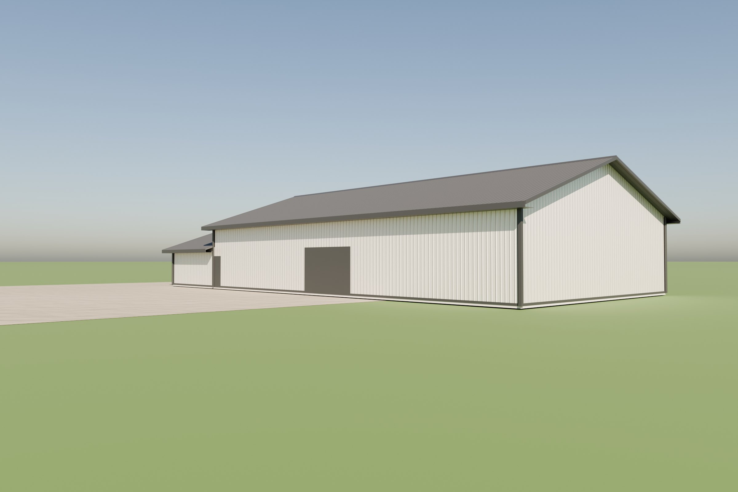
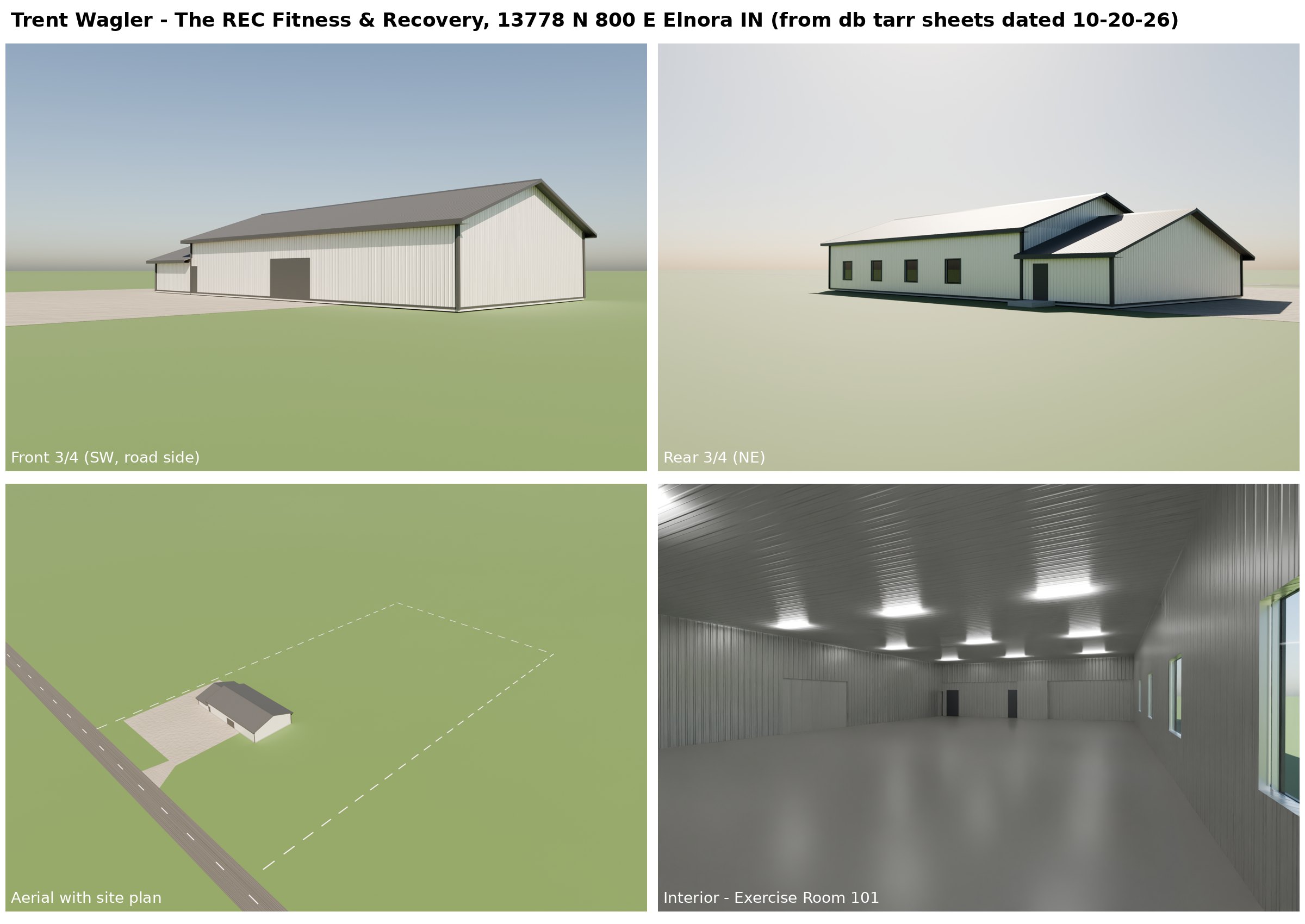
From the southwest: west side with the 12'×8' overhead door, south gable
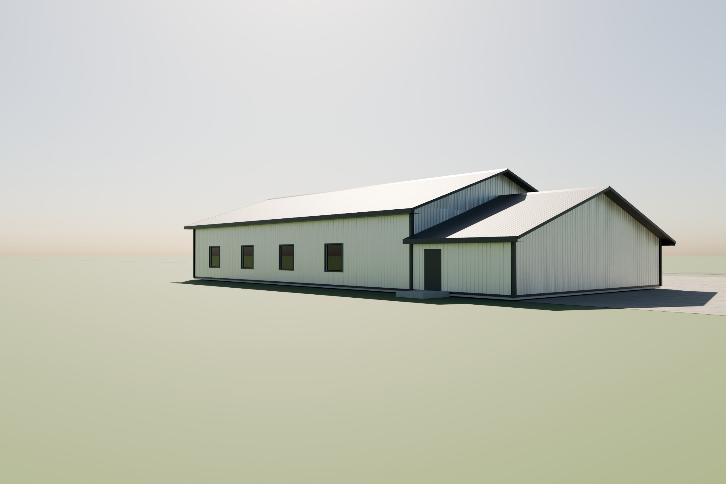
From the northeast: east windows, entry door and the 9' low wing
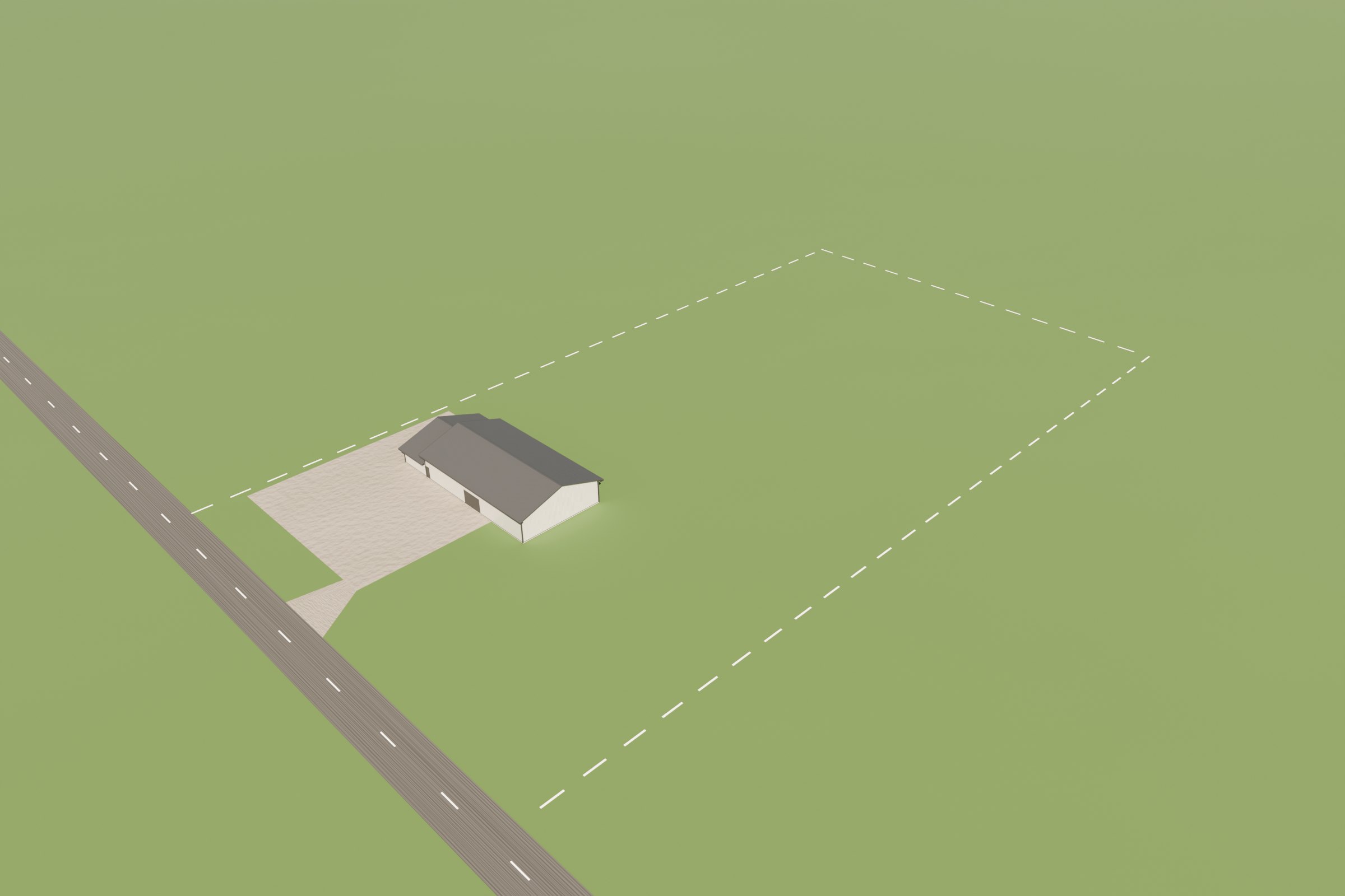
Aerial with the gravel drive off 800 E
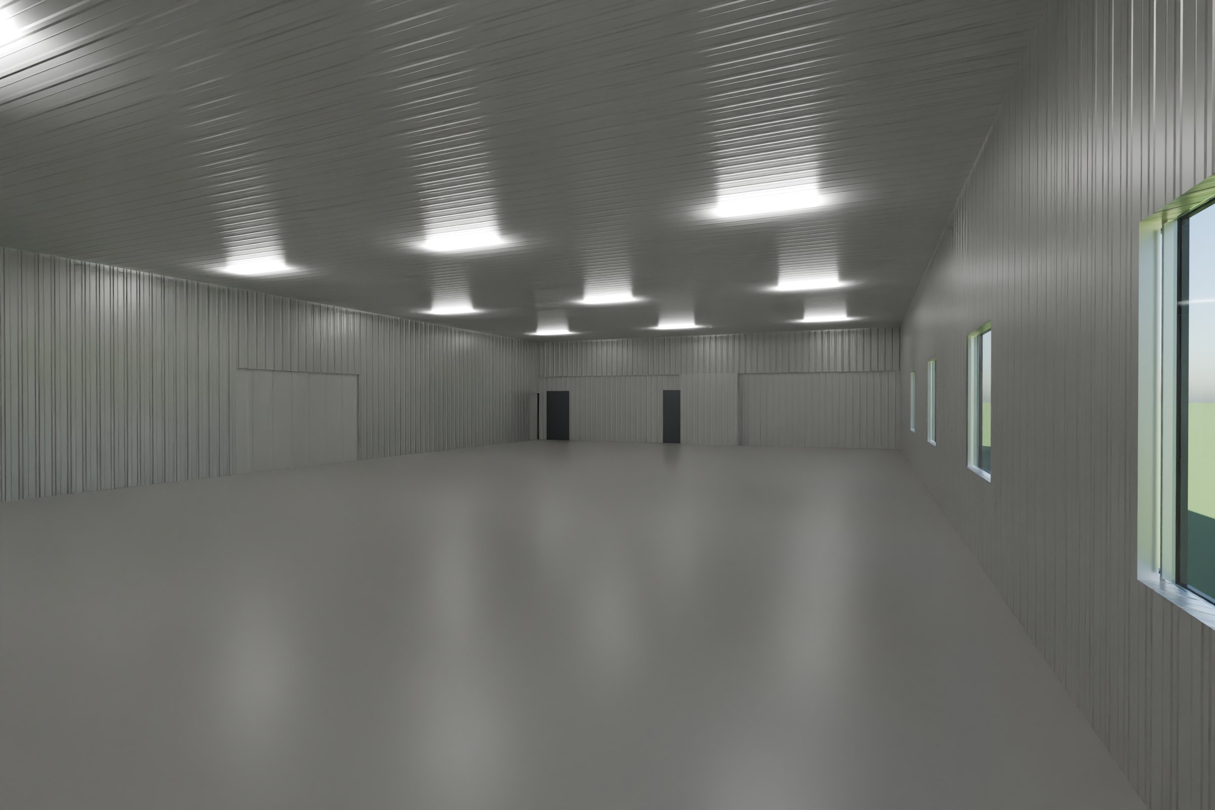
Interior: 101 Exercise room, 14' metal ceiling
Contact sheet of all views

Interactive 3D model

Drag to orbit and pinch or scroll to zoom. Use 🎨 Colors to try roof, siding and trim colours, and the side panel for layers, the Foundation view, the exterior concrete, interior and framing views, the site view and walk mode. Walls near the camera hide automatically (turn it off under Display). Click a part for its details; long-press (iPad) or right-click any part to hide it.

Open the model full screen Download the model (GLB)

Key dimensions

Building

Footprint100'-0" × 48'-0"
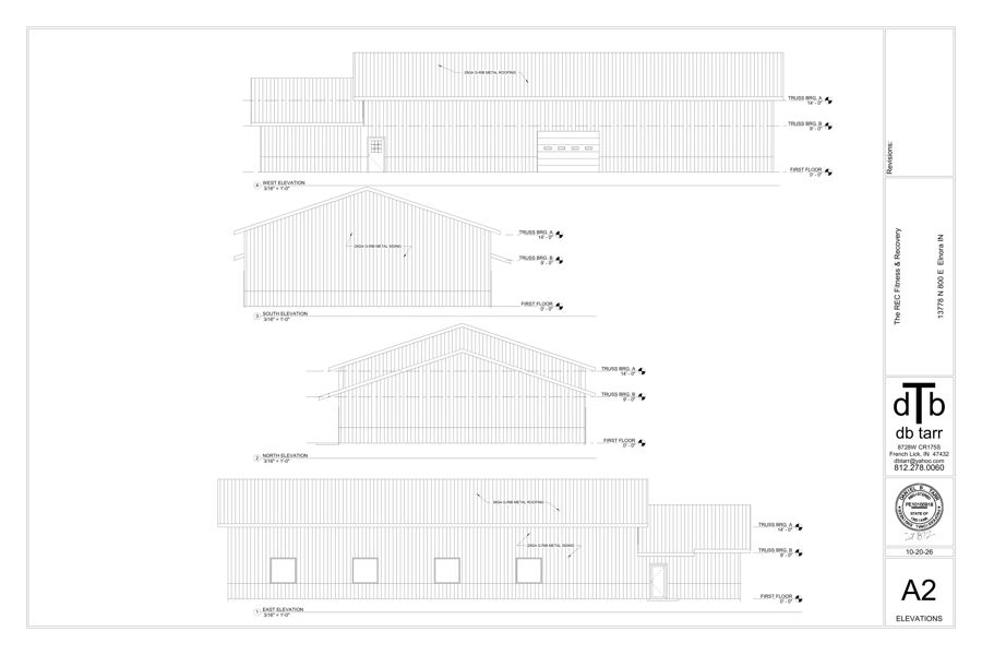
Main section80' long, truss bearing 14'-0"
Low wing (north)20' long, truss bearing 9'-0"
Roof4/12 ASSUMED, 2' overhang ASSUMED
Post bays8'-0" (A1)

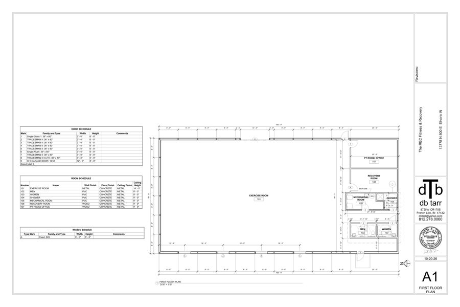
Openings (A1 schedules)

  • Door 9: 12'×8' overhead (west)
  • Door 8: 3'×6'8" Tradesman II 9-lite (west)
  • Door 1: 3'×6'8" full glass entry (east) with stoop
  • Doors 2-7: 3'×6'8" interior
  • Four 5'×5' windows on the east wall

Rooms (A1)

  • 101 Exercise room – 14' ceiling, metal walls
  • 102 Men, 103 Women, 104 Shower, 105 Mechanical – PVC walls, 9'
  • 106 Recovery, 107 PT room / office – wood walls, 9'

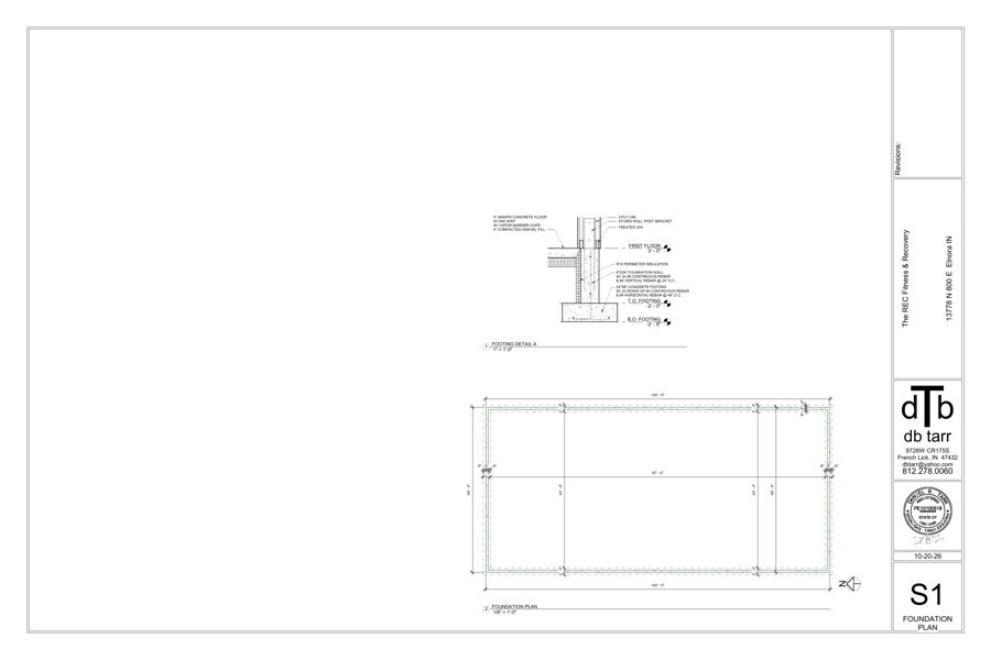
Structure (S1)

  • 29 ga G-Rib metal roof and siding
  • 3-ply 2×6 posts on Sturdi Wall brackets
  • 8"×24" foundation wall, (2) #4 cont. + #4 vert. @ 24"
  • 24"×8" footing, T.O. -2'-0", R10 perimeter insulation
  • 4" 4000 psi slab, 6×6 WWF, vapour barrier, 4" gravel

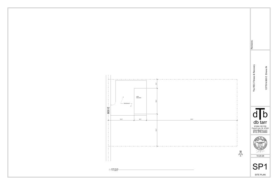
Site (SP1)

  • 100' from County Road 800 E
  • Lot lines 35' north, 125' south, 352' east of the building
  • Gravel drive off 800 E

Drawing sheets

Graber Post drawings, 10-20-26, forwarded by Dustin Stoll. Click a sheet to enlarge; PDF links open the original.

SP1
SP1 – Site plan · PDF
A1
A1 – Floor plan, door / window / room schedules · PDF
A2
A2 – Elevations · PDF
S1
S1 – Foundation and footing detail · PDF
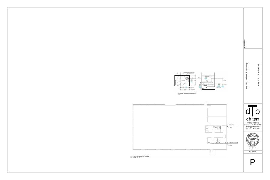
P
P – DWV plumbing plan · PDF

Assumptions

Anything not shown on the drawings is labelled ASSUMED and will be confirmed with you.